Toasty is a 11.7L 3D printed small form factor PC case thats different from the standard metal box. Inspired by retro styled radios and toasters, Toasty measures at 260 X 260 X 174 mm, and is small enough to fit on most tables with minimal compromise to thermals and performance.
Toasty features interchangeable front/side panels to suit your preferences where one of such panels integrates a small SPI LCD to show PC stats or Spotify now playing screen that the set of switches toggles.
Currently I have been using this case for over half a year and still holds up perfectly despite the heat from the components inside. Parts consists of a R5 3600, GTX 1080 TI, 16gb ram and 550W PSU. CPU temperatures idle at 50C and 80C on load while GPU idles at 30C and 80C on load hence airflow is pretty respectable.


Case Specifications
- ITX motherboard
- FLEX ATX PSU*
- Max 220mm GPU length
- Max 55mm CPU
- 3X 2.5inch HDD OR 1X 3.5inch HDD
- 300mm PCIE riser cable ( 180° flat version ) ( DO NOT GET 90° )
*my own build uses a proprietary sized PSU I got for cheap but the files I published uses flex ATX
How does it come together?
The case mainly consists of 2 main parts, the outer shell and the inner spine. All components are mounted on the inner spine and the outer shell slides over the whole assembly. I tried my best to pack all the components as tightly as possible to achieve such a small size. Heres a gist of how the whole thing comes together:


Build Guide
Parts needed
Additional Components:
- Handful of M3 & M4 Screws, Nuts and Heat Inserts
- 12mm PC power button
- USB 3.0 + USB + audio jack front I/O board
Optional Components:
- Pi Zero W
- 2.4 inch SPI LCD
- 2X LEDs
- Toggle switches
- Flick switches
- 330 ohm resistors
- 10K ohm resistors
Print Settings
Printables link here. I welcome remixing or modifying and .f3d / .stp files will be included.
Printed with a 0.6mm nozzle, total print time takes about 2 days with ~750g PLA and ~120g PETG. Although I would recommend you might as well print the whole thing in PETG.
You have 2 choices for side panels under “Side panels” and 3 choices for front panels under “Front panels”.
I turned ironing on for all side and front panels for a nice smooth outer finish.
Use paint on supports on these edges below and be sure to select “For support enforces only” for supports. I did this so that I wont need to waste filament on the bridges in the print.

Everything else should be pretty easy to print.
Heat inserts
Im using M3 OD3.6 / L5.7 (Blue) and M4 OD6.6 / L5 (Green) Heat inserts that the holes of model is modelled after. You can problaby get away with using similar sized ones.

Melting parts together
The side panels and main shell are melted together using a soldering iron. You could use glue too but I felt that this was easier for me. I have a TS100 temperature adjustable one on hand so I did all this at 220C to eliminate fumes.
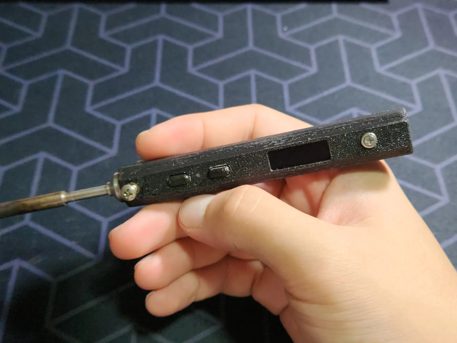
Mix-n-match switches and LEDs
This whole area is drilled and sanded out so its really up to u what configuration you want to use. For the Pi-Zero + Screen configuration, its pretty standard GPIO stuff. Your keywords are - 330 Ohm Pullup Resistors for the switches and 10K Ohm resistors for the LED.

Pi-Zero + SPI screen display
This part is still a a work in progress! I found that my Pi Zero W was too slow to render webpages pages fast enough to switch between tabs with the switches and I currently am unable to get ahold of a Pi Zero W 2. Hence, it currently only shows the spotify now playing page on startup.
I used FullpageOS for the main operating system as it is used for loading up and displaying any webpage on boot without any prior setup. This can be found in the Raspberry Pi Imager app under Other specific-purpose OS. You would still need to install python and the fbcp-ili9341 drivers for the display to work. More info can be found in my DeskTV guide under “Software Portion”.
Bringing it all together
At this point you can put in all your components, starting with the PCIE riser. Take note that the PCIE riser is screwed in like so.

As the PCIE riser is seperated into multiple wires I also taped it up with some heat resistant cloth tape so that it won’t catch onto the shell during assembly later on.

The hard drive goes in like this. It isnt the most secure fitting method as its held on by 2 screws to the spine and a supporting piece at the bottom but this PC wont be physically moving around much anyway so it will do.

Fitting the shell in is pretty finnicky but heres how I did it. You have to “hook” the shell over the GPU power cables and slowly slide the shell over the whole spine assembly.

Then screw in the front panel.

Lastly, screw in the back panel.

Congrats for making it through the whole guide and do enjoy your new Toasty! I would love to see your takes on Toasty so do make sure to share your makes!